Hi,
Today I will show you, what is in my 8 channel remote switch system. It is for to control (switch on/off) electronic devices, which normally haven’t got any IR reciever on them.
The very first idea was just to catch some IR transmission, which comes from a remote controller (of a TV, or an old video player, etc.) with an AVR. I usedTSOP31233 to recieve the raw data. As I couldn’t find any general description about IR transmission protocols or anything like this, I had several unsuccesful try. But finnaly I found out a quite usable algorithm to identify the difference or the conformity between two buttons on a controller. Some minutes after this, I had the plan :) .
I was starting to design an universal remote switch with these properties:
- it has to be usable with many IR controller (can learn the buttons anytime) which has a compatible frequency with the reciever IC
- it has to control several 230V plug sockets and 5V DC supply outputs
- it has to be standalone (one possible solution could be an IR reciever on a PC’s serial port, and the outputs are on the parraral port, etc..)
- it has to recieve commands from computer directly (by AVR’s USART, converted to USB)
- it has to got timing function to automatically switch off an output after a given time (like sleep function on TVs)
The first issue was, to get a general algorithm, which is usable for all the remote controls. I tried out some different controllers, and except one of them, the signal structure was the same:

TSOP3123x produces inverted output, so when it gets modulated IR signal, it outputs 0V, when no IR signal comes (between two signal or in idle time), it outputs the VCC.
For all data bit transmission, the signal always turns from high to low, then back. In case of bit “0”, this time (between two high-to-low transition) is half long than in the “1” bit case. Usually a controller sends out 32…60-70 (same for all button in one controller) bits for a button and there are only a few bit (content) difference between two buttons.
When a button is pressed, the controller transmission starts with a startbit, which is several times longer then a databit. For my Samsung TV’s controller, the startbit is six times longer, for an 3M projector’s controller, it is 12x longer. It will be used to identify the correct data bits. I wrote a test program which dumps out the measured time between the high-to-low transitions (on USART). From this, you can identify your controllers characteristics. Here is the test circuit:

And the test program: link.
With this, you can get how many times longer the startbit is (you have to define this to the main program), and the data length. As we don’t have to reproduce the signal (just identify it), the reciever needs only the databits (or just an identical piece of it) and the startbit multiplier (see in the code), but we don’t have to store the exact time values. As I saw, if (the first or the last) 32 bits are stored for a button, that should be enough. So the definite design has these elements:
- atmega8
- TSOP31233
- FT232RL for the USB connection (of course you can use avr-cdc, or just a simple MAX232)
- three 230V output, more would be cool, but I haven’t found more usable parts for it (I found an old 3 socket distributor with separate wiring option, but no more)
- 5V input relays for the 230V outputs
- five 5V output to supply my other AVR devices :) (mood lamp, etc..)
- resistors, transistors, leds, transformator, diode bridge, buffer capacitor, 7805, heatsink, enclosure, fuse, etc. :)
The schematic:

And the board:

Now I know, it would be more cool if I use N channel MOSFETs for switching the 5V outputs, but it works with transistors as well. The TSOP is connected bt that 4 pin header (JP1), the AVR’s INT0 pin is connected to the output os the IR reciever. The 4’th pin (with the R10 resistor) if for a LED which will give feedback when a button press was recognised (one blink for a normal button, continous blinking for the sleep button).
Finnaly I bougth some stuff to produce PCBs, with toner transfer method. There is a lot of howto on the net, I won’t describe, but it’s really cool and almost professional :). And the best is that, now I can use SMD components (as I couldn’t use with breadboard PCB, like FT232, which is not available in DIP package), so form now on, the sky is the limit ;). After a short week of experimentation (cursing :)), I found the correct paper, printer and temperature for the ironing.


The software has three inputs. One is the remote control itself, and the other is the AVR’s USART. The plan was containing that, I want to control the outputs from computer, (then I can connect it to my router and I can turn on my evaporator from my workplace before I go to home :) ). It has a fully functional prompt with commands to turn on/off outputs, set sleep to an output, initiate learning, etc. . The only thing what the remote control can’t do, is to trigger the learning of the buttons, because when the device doesn’t know the remote control… ok, I think you understand it :) . So if no USB connection is available, the device has a third input to start learning. As the learning function is not offen used, I took it to one of the pins, which is one on the ISP header (PINB4) anyway. When it learns the buttons, the actual output is switched on while it can recieve enough sample to store (you can define it in the code). The AVR stores the learned buttons (8 for the 8 outputs, and one for the sleep function) in it’s internal EEPROM. When you press the sleep button, it waits for an other button, then it turns on that output for ~30 min, than off (you can trigger a sleep for every output in minutes step from computer). You can set some value before you compile the program, for example the amount of the same samples which the device waits while it is learning.
You can compile it with and without any USART communication, and in debug mode to dump out every recieved IR data on usart.
Here are some picture of the complete device:
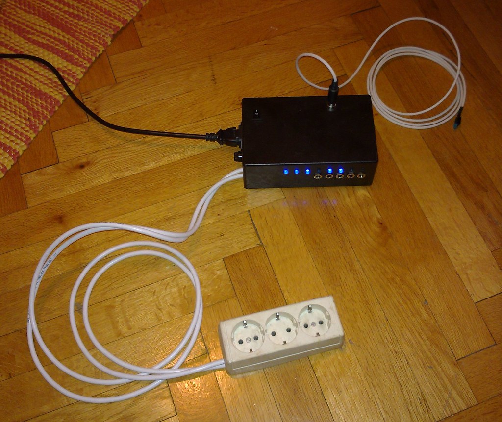

The five 5V outputs are on DC jack connectors (the first three LEDs are for the 230V outputs)

The plug and the fuse:

The TSOP and the feedback LED are connected via an s-video plug:


The rest of the details is written in the code, download it here (with the eagle files): link.
If you have any question, or just you like this project or built it, as usual, send a comment please!
Cheers.
sdsdsevaporator