Hi everybody,
Today I will show you, how I built my digital clock. Many years ago, when I didn’t know what the microcontroller is, and in the secondary school we learned about TTL logics, I couldn’t imagine how to build, for example a digital clock. Now I already have one :)
The hardware
It is based on a reused 3 and 3/4 digit, red LED display from an old, damaged digital clock. It has a type printed on it: FTTL 655S. It was originally driven dy an NLE2062 IC. I think this type is very common in the low quality/price alarm digital clocks, so you can easily find one usable display. So I desoldered it and started to find out the internal setup of the LEDs. Finally I found a pdf about a clock kit, and there was the same type of display.
The structure is not so understandable at first. The main thing is that, it has two common cathode, and many common anode, which are connected to two LEDs, one-one with the cathodes. So we will need to multiplex the displaying with the two cathodes, and remembering that, the anodes are controlling different segments when the other cathode is used. For the clock I needed 27 segments (3x7 for the full digits, and 6 for the first) in 24 hour mode, and the blinking colon. If we look at the schematic of the display, we count 15 anode pins for these 28 led segments. Ok, 15 pins on the controller. We need two more for the cathodes. The sum is 17. The atmega8 has 22 programmable IO pin, if we don’t count the RESET pin and using internal clock source. For the proper time, I wanted to use some kind of RTC (Read Time Clock) IC. The choice was the Dallas’s DS1307. It can handle two VCC, ideal for battery backup and it uses I²C. Because there are five free pins after the segments, and I²C costs other two, there are 3 more. I used two for buttons (hour and minute adjusting).
The software
The last difficult thing was the software. There were too many entities about the segments’ place and the numbers… So I made two different group.
First is the characters look, what I wanted to use. It has no connection with the digits on the display, it just describes the lighting segments of a digit. I’ve put the data in an array:
1
2
3
4
5
6
7
8
9
10
11
12
13
14
15
16
17
18
19
20
volatile unsigned char number_look[17]=
{
	0b0111111,	//0
	0b0000110,	//1
	0b1011011,	//2
	0b1001111,	//3
	0b1100110,	//4
	0b1101101,	//5
	0b1111101,	//6
	0b0000111,	//7
	0b1111111,	//8
	0b1101111,	//9
	0b1110111,	//a
	0b1111100,	//b
	0b0111001,	//c
	0b1011110,	//d
	0b1111001,	//e
	0b1110001,	//f
	0b0000000	//empty
};
I made hexa letters as well.
The second thing is the connection between the segments physical (which digit’s which segment is it) and logical place (which cathode and which AVR pin is connected to it). Then to handle the segments differently, they has to got some ID, practically a number. So I added a number to all the physical segments:
 Now I could index an array by these numbers, and the array itself stored the logical properties of the segment, such as:
- the port on the AVR (2 bits to indicate PORTB,C or D)
- the pin of the port (3 bits to indicate the PIN 0-7)
- the cathode ID (1 bit: 0 or 1)
That is 6 bits at all, so one byte is enough. So I soldered the pieces together and I didn’t have to mind the exact IO pin for each segment, because I will map them by this array… I just left the I²C and two pins for the cathodes free, then just soldered the anodes in randomly (also the colon). After it, I wrote a program which was set one bit on one PORT to true, and by pressing the button it changed to an other (one cathode was turned on as well of course). By this, I could identify all the LEDs place, cathode and the PORTs connection. I made tables of the pins and the segment ID relations, two for the two cathodes. Based on this, I could make the character array:
1
2
3
4
5
6
7
8
9
10
11
12
13
14
15
16
17
18
19
20
21
22
23
24
25
26
27
28
29
30
31
32
33
34
35
36
37
38
39
40
/*
0th bit (LSB): anode ID, 0 or 1
1st-2nd      : PORT ID
                PORTB: 0
                PORTC: 1
                PORTD: 2
3rd-5th      : pin number 0-7
6th-7th      : no meaning (0)
*/
volatile unsigned char segments[28]=
{
	0b00011000, //0
	0b00010001, //1
	0b00101001, //2
	0b00100000, //3
	0b00100001, //4
	0b00000000, //5
	0b00011001, //6
	0b00010011, //7
	0b00000011, //8
	0b00001011, //9
	0b00001010, //10
	0b00101000, //11
	0b00010010, //12
	0b00000010, //13
	0b00011010, //14
	0b00000000, //15
	0b00101100, //16
	0b00101101, //17
	0b00111001, //18
	0b00011011, //19
	0b00000001, //20
	0b00001101, //21
	0b00110001, //22
	0b00100101, //23
	0b00100100, //24
	0b00111000, //25
	0b00001100, //26
	0b00110000  //27
};
Based on this array, I could draw the schematic:
Now we need only the algorithm to draw different characters on different digits. We need to change the used cathode periodically, so we will draw the half of the ‘frame’ at once (for this, a timer interrupt was used, to keep the period time). An other thing is to find a segment. Because they have ID, and they are in logical order, we know that the first digits ‘a’ segment the 0th, the second’s is the 7th, the ‘g’ of the last digit is the last (27th) and so on.
Other tasks of the AVR:
- reading the time on the i2c bus is the only task of the main() function
- to modify the time with the buttons, I used the two external interrupt pins, INT0 and INT1
- a little fun stuff was implemented into it, to make my clock different :). This is a little animation when the minute is changing. The display fills up from the top, then become empty before the changed time appears.
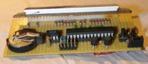
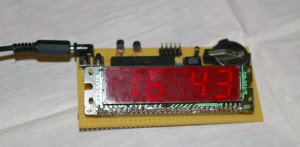
Some pictures of the result:
Here are the code and the schematic
Here is the binary hex if you don’t want to compile the project. AVR clock speed shall be set to 8MHz.


