After moving to a new place, I’ve found new challenges to solve here and there. One such unresolved thing was the hot water circulation control. In this post I present one possible solution which is according to the user’s behavior.
The problem
This is a tiny project to control a water pump. In a typical domestic hot water system, there is a common problem that the water gets cold in the pipes if some faucets are too far. So you have to waste a lot of water (and time :) ) until you get the hot water, if is was not used recently.
The base of the solution is to build also a returning pipe between the last faucet and the boiler or hot water tank, where a pump can circulate the returning water, so that keeping the pipes hot.
The big question is that based on what event are you going to circulate the water? After a bit of googling you can find these ideas:
* Timer switch, programmed for the typical hot water use times (morning, evening).
* Thermostat: you somehow measure the returning water’s temperature and control the pump when needed.
* Detect water usage: there are solutions which can detect when you use any faucet in the house. So you can trigger the circulation by using the e.g. shower for a second, than wait until the hot water arrive before you really start to use it.
Solution
I was not impressed by any of the solutions above, even not with any combinations. Fortunately I had the pump and the returning pipe built in, so I can control it how I want.
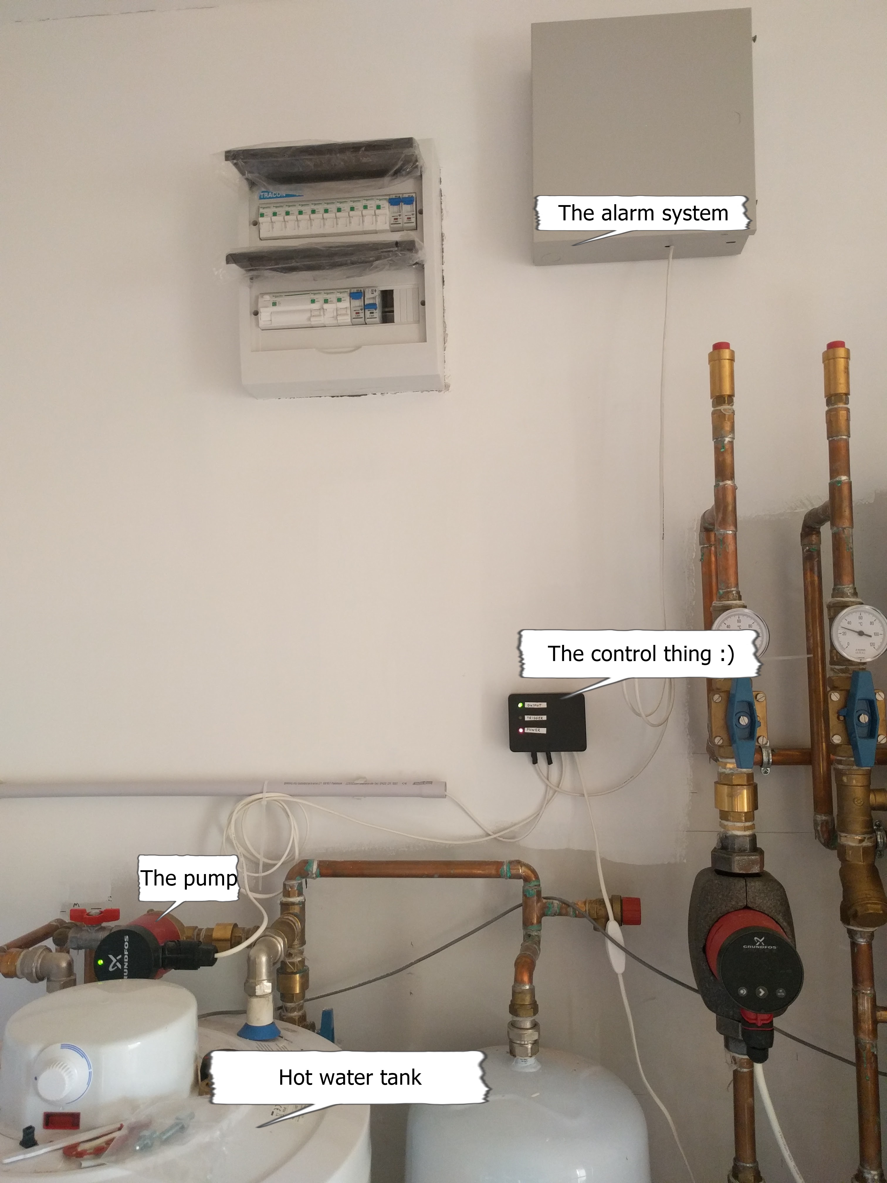
My solution is based on the detection of motion in the house. I have a basic alarm system in the house with passive IR motion sensors in every rooms. The idea is that before every water usage, the people have to walk to the desired faucet. There might be additional time before you need the hot water, like you use the toilet first, for instance :). This time is most probably enough for the pump to get hot water everywhere.
I inspected my alarm system and found a programmable output on the board which can follow any selection of the motion sensors status, so it can trigger this AVR project, which will control the pump for a predefined time.
Also there is a hold timer, which will not switch on the pump ON again if the water is supposed to be still hot in the pipe.
My resulted timers are: 5 mins for every trigger and 25 mins hold-off. It worked out very well.
The code is written in C++ and using my base library from here.
HW:
- ATTINY45@1MHz
- Opto couplers for both input from the alarm system and towards the output
- 12V relay to control the pump
The essence of the solution is obviously the trigger which comes from the alarm system. AVR only enlarges the trigger time from the movement interval to the necessary time which is needed for the water to take the loop.
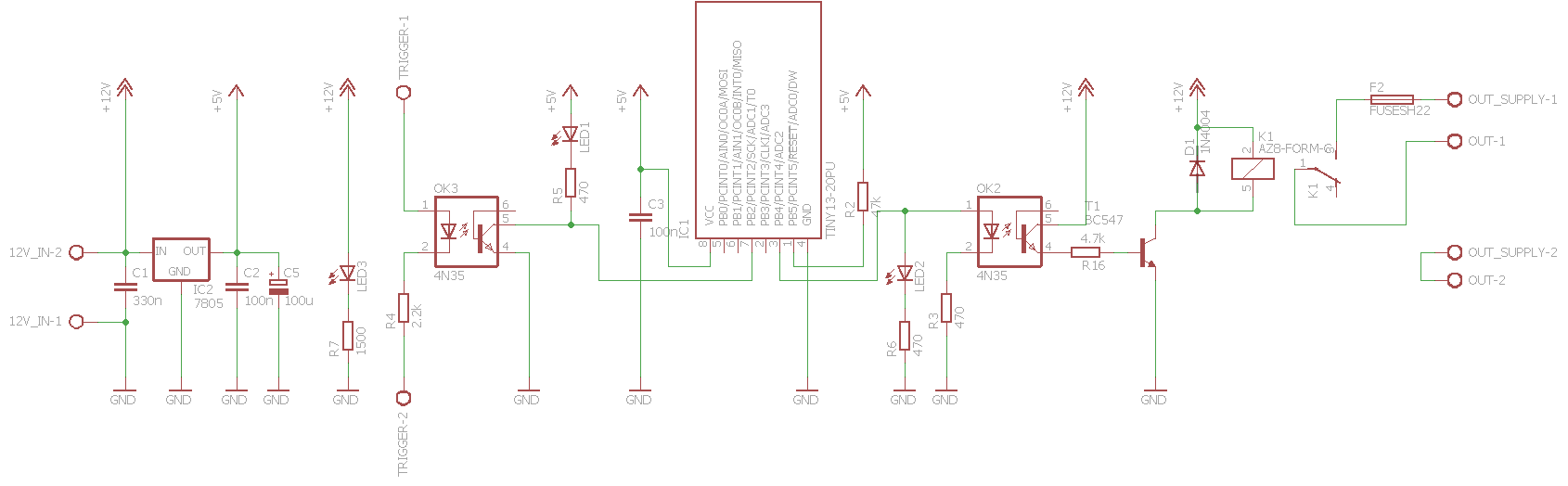 The schematic is crazy simple: 12V-5V conversion, input receiver part, output part.
The code is also very simple as you might think. It has to only maintain two time intervals, which are connected. The fancy part is that I used my AVR C++ library, presented in the last post. There I already created the low-level parts for this application in the base library:
- Soft timer set: controls arbitrary counters, controlled by one real timer
- Timed output: timer handler implementation to set a GPIO to 1 until a predefined time
The missing part is the hold-off login, which became also a similar class to the timed output. This is the Trigger class.
1
2
3
4
5
6
7
8
9
10
11
12
13
14
15
16
17
18
19
20
21
22
23
24
25
26
27
28
29
30
31
32
33
34
35
36
37
38
39
40
41
42
43
44
45
46
47
#include <avr/io.h>
#include <avr/interrupt.h>

#include "SoftTimerSet.h"
#include "TimedOutput.h"

#include "Trigger.h"

//Config BEGIN
#define OUTPUT_ON_TIME 300
#define TRIGGER_HOLD_OFF_TIME 1500
//Config END

#define OUTPUT_PORT_MASK 1<<4
#define INIT_OUTPUT()  DDRB|=OUTPUT_PORT_MASK;                                 // PORTB3 -> output
#define INIT_TRIGGER() PORTB|=1<<2;MCUCR|=1<<ISC01;GIMSK|=1<<INT0; // PORTB2 -> input (by default), activate pull-up and falling edge interrupt

#define INIT_TIMER0() TCCR0B|=1<<CS02|1<<CS00;TIMSK|=1<<TOIE0; // Set TIMER0 prescaler to 1024; this will cause 3.8 tick/sec (~4HZ)
#define SECOND_PRESCALER 4
volatile unsigned int overflow_counter = 0;

SoftTimerSet<2> gSoftTimerSet;
Trigger *gTrigger = 0;

ISR(TIMER0_OVF_vect) {
  if(++overflow_counter == SECOND_PRESCALER) {
    gSoftTimerSet.tick();
    overflow_counter = 0;
  }
}

ISR(INT0_vect) {
  gTrigger->activate();
}

int main(void) {
  INIT_OUTPUT();
  INIT_TRIGGER();
  INIT_TIMER0();
  TimedOutput output((volatile void *)&PORTB, OUTPUT_PORT_MASK, OUTPUT_ON_TIME);
  gSoftTimerSet.add(&output);
  Trigger trigger(&output, TRIGGER_HOLD_OFF_TIME);
  gSoftTimerSet.add(&trigger);
  gTrigger = &trigger;
  sei();
  while(1);
}
Pretty easy to consume I think. I became a C++ fan on AVRs :). As usual, my AVR projects are created with the official AVR studio, unfortunately available only on MS Windows. Anyway it would compile just fine under linux with pure avr-gcc. I was simply lazy to create Makefile for it.
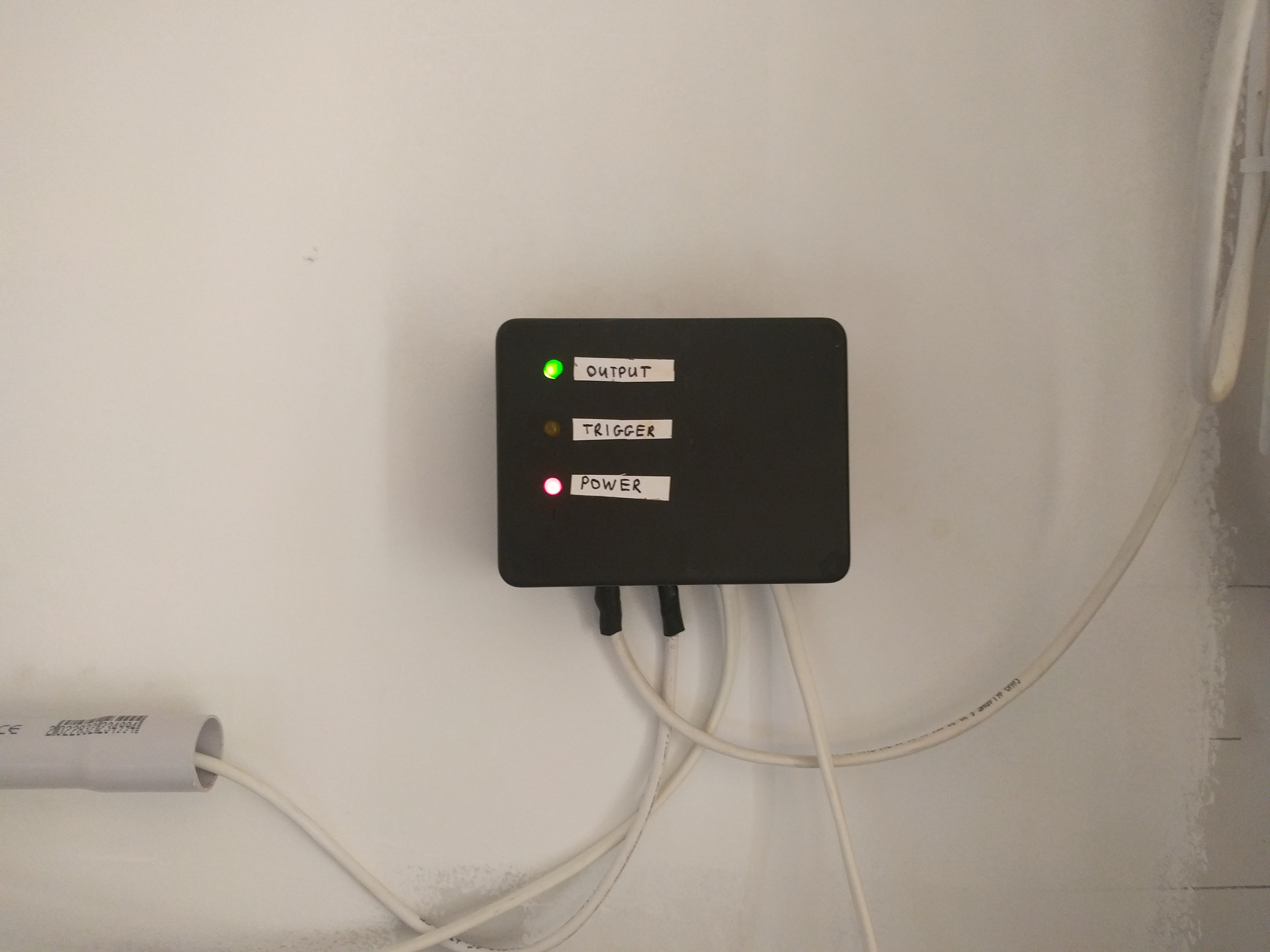
The result
Some visualization of the end result:

Resources are available in the following repo on github.
You can directly download the hex file from here.