This post is about my irrigation system built last spring. I thought I can create a smarter sprinkler computer than the stock ones. The design constraints were roughly these:
- ~250 m2 of lawn as subject for sprinkler irrigation
- ~100 bushes as subject for drip irrigation
- Fortunately the site is horizontal, but
- Unfortunately is divided into two halves by a sidewalk
- Cost efficiency, as usual :)
The result after one year is fortunately the green lawn, as expected: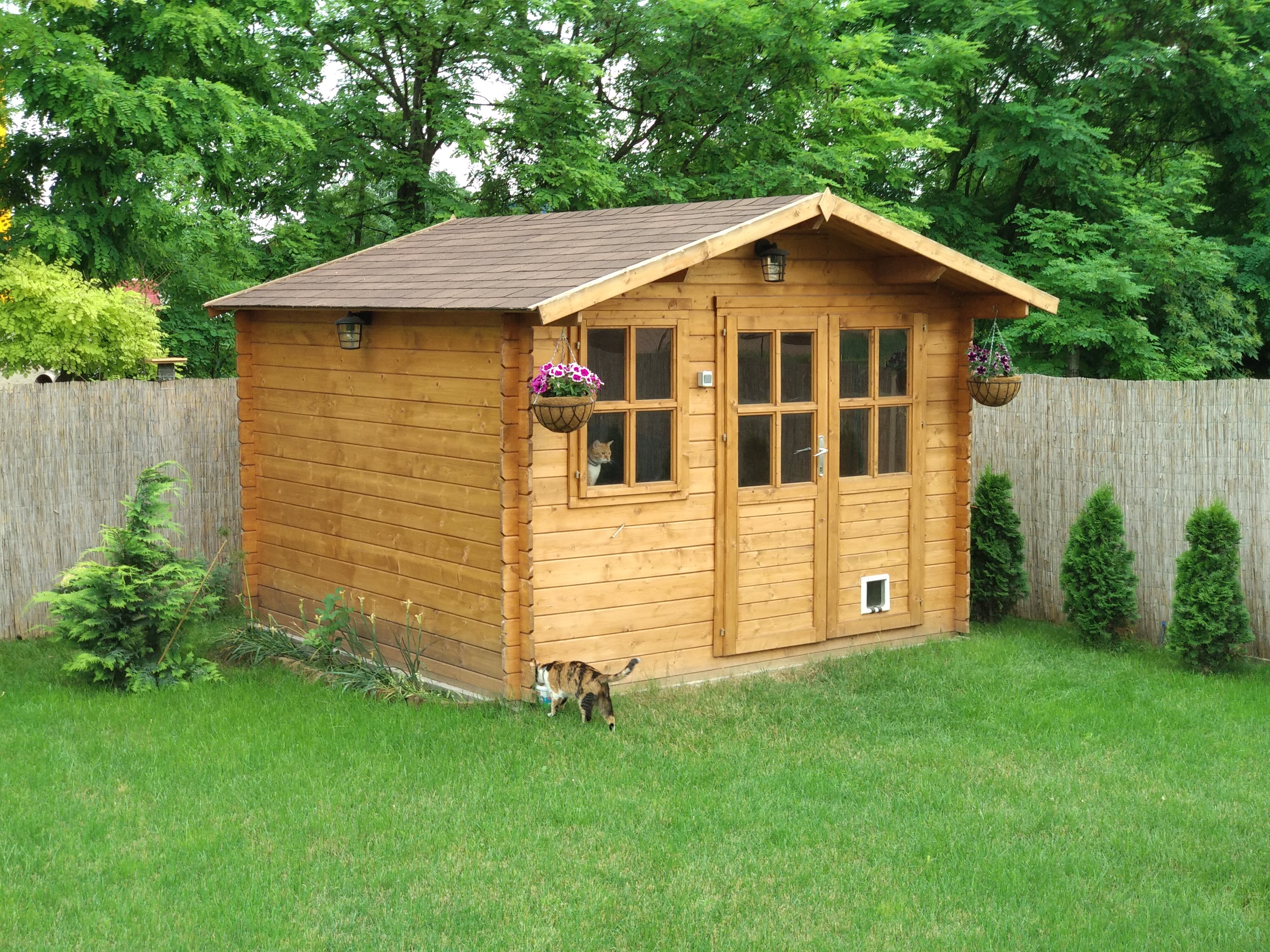
My derived requirements against the end result is:
- Possible remote control, preferably over WiFi and web browser
- Control unit is installed in a wooden house, so has to be partly weatherproof
- Rain detection, maybe even more in the future
- Water source is a drilled well
- The water source is used besides the irrigation, with a regular faucet.
- All the water related things are hidden under the wooden house in a pit. This is good because it does not get under 0 Celsius even in the coldest winter, so the water will not freeze in the pump.
I ended up with my ever first Raspberry PI project. There is not any AVR here :).
The real hardware
Unlike my other DIY projects, this one has the extraordinary task to realize e.g. the irrigation water supply network if you prefer end-to-end DIY. This is starting with dig the whole garden :). It took roughly five very long Saturdays for us. According to the well and the pump capacity, we had to create 4 individual water circles. three for the sprinklers and one for the drip lines. We have the luck to have the idle water level starting only 4m under the ground so we have the (more cheaper) pump on the surface and not in the well.
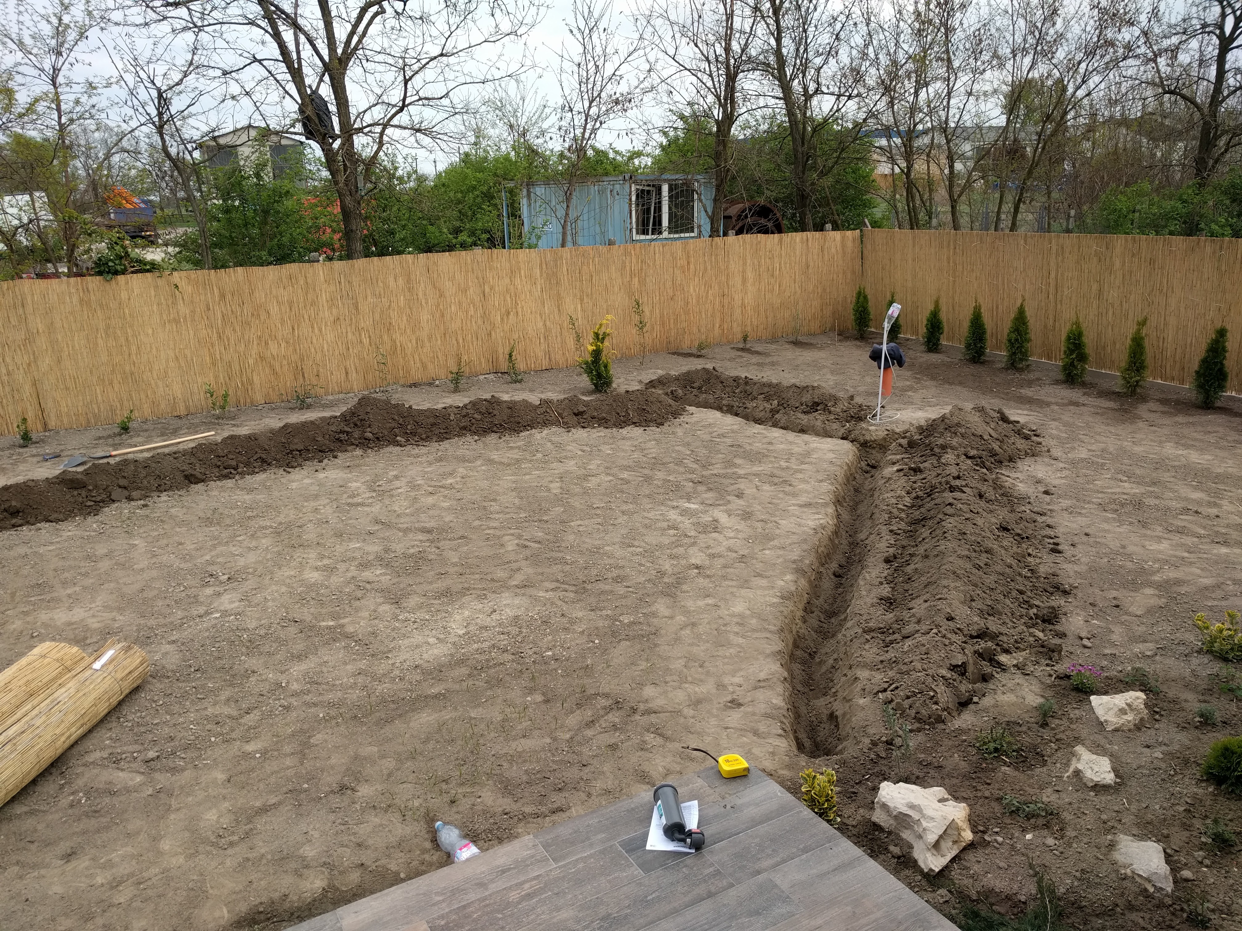 Dig…
Dig…
 … dig alot …
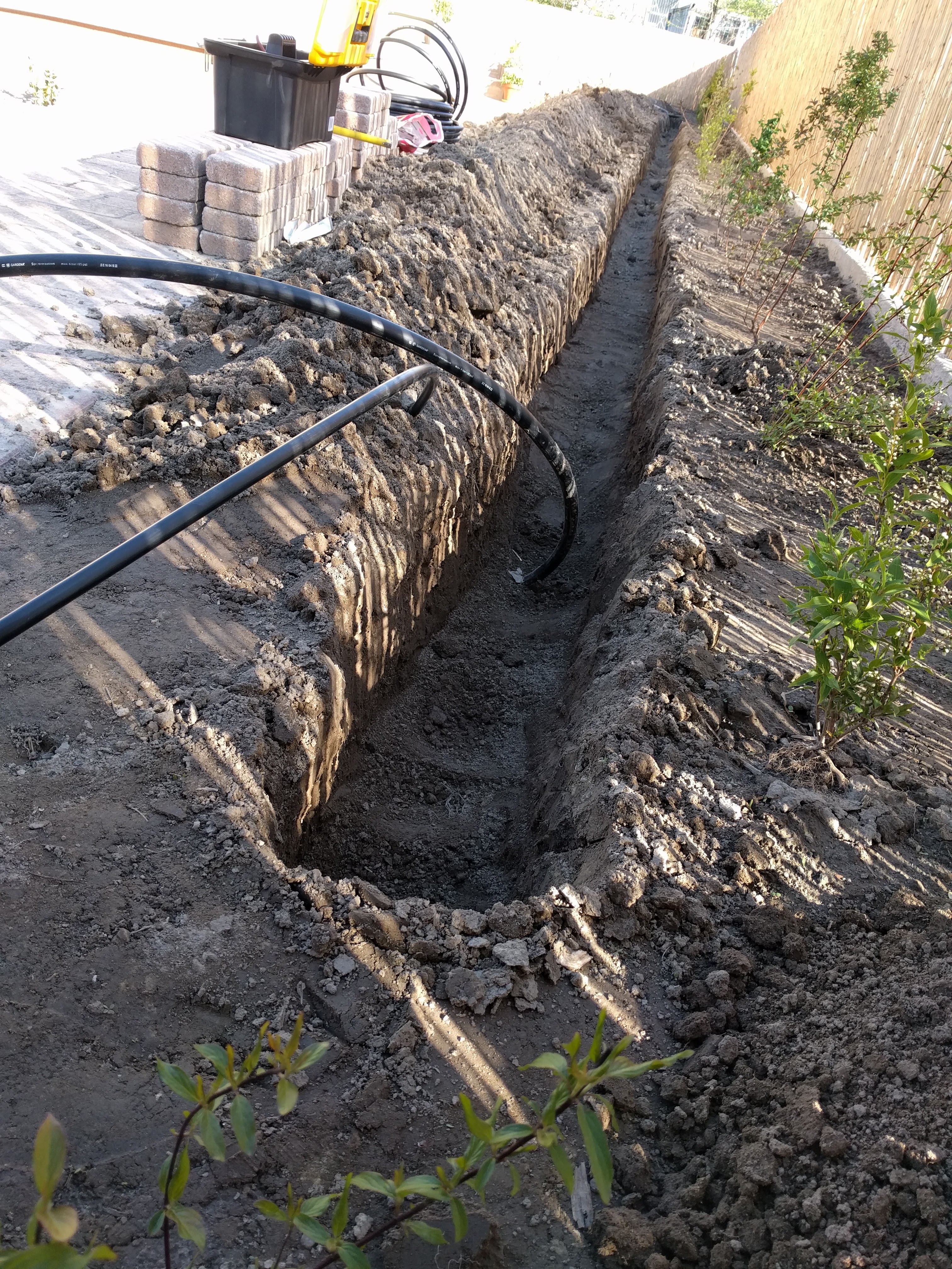
 Even sometimes under the surface.
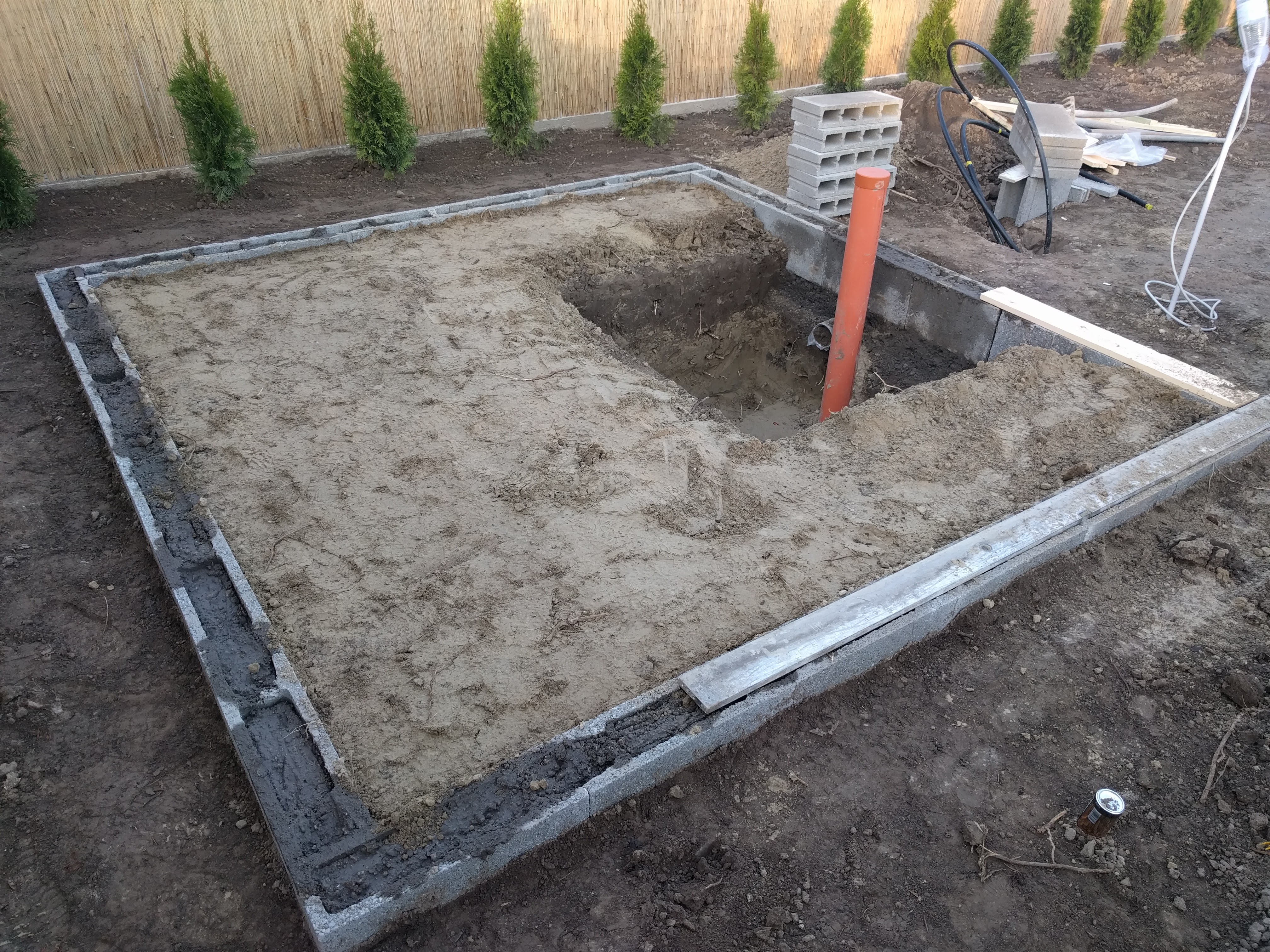 Eventually the wooden house is progressing. The well still stands off.
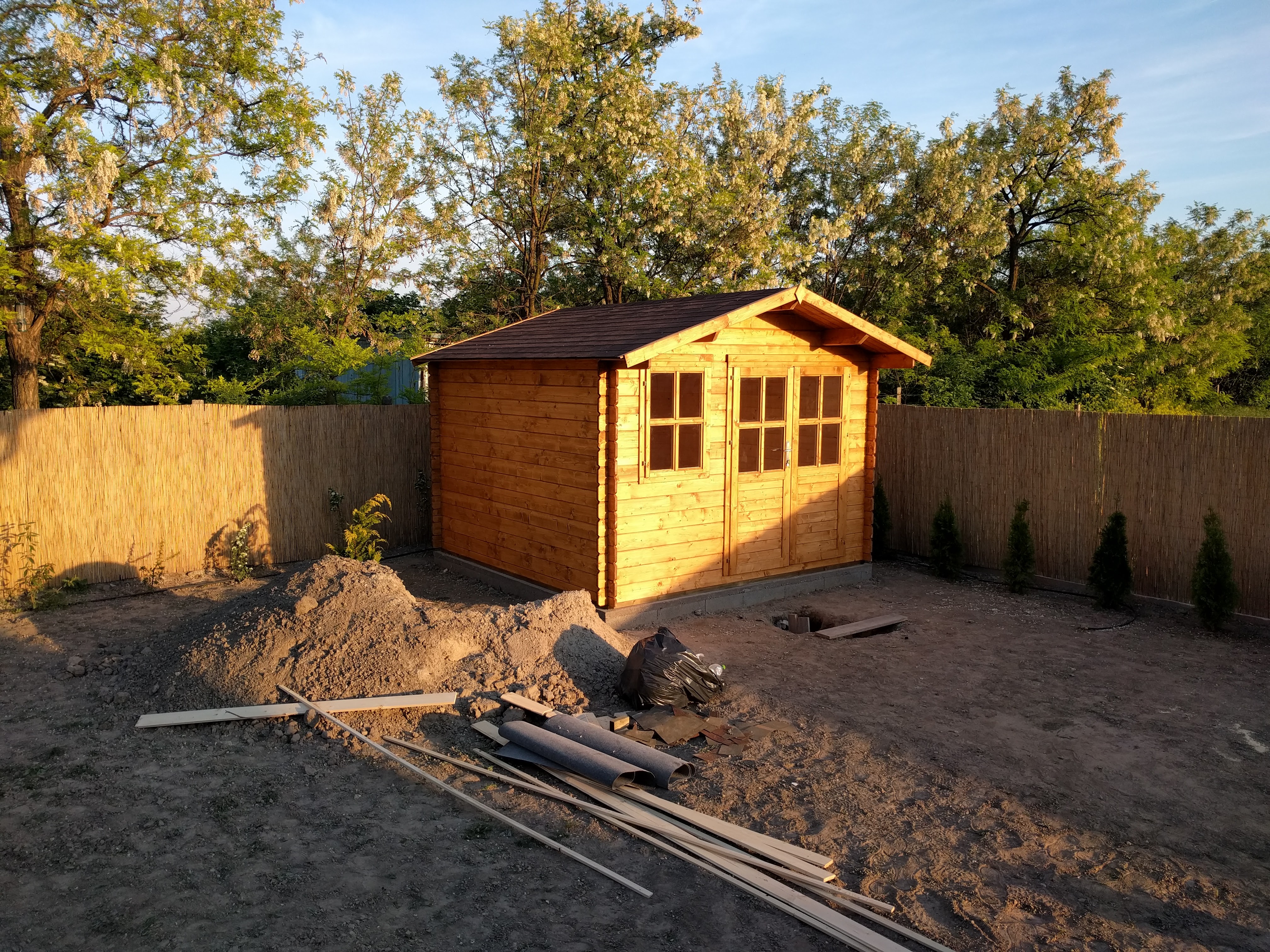 Aaand there it is.
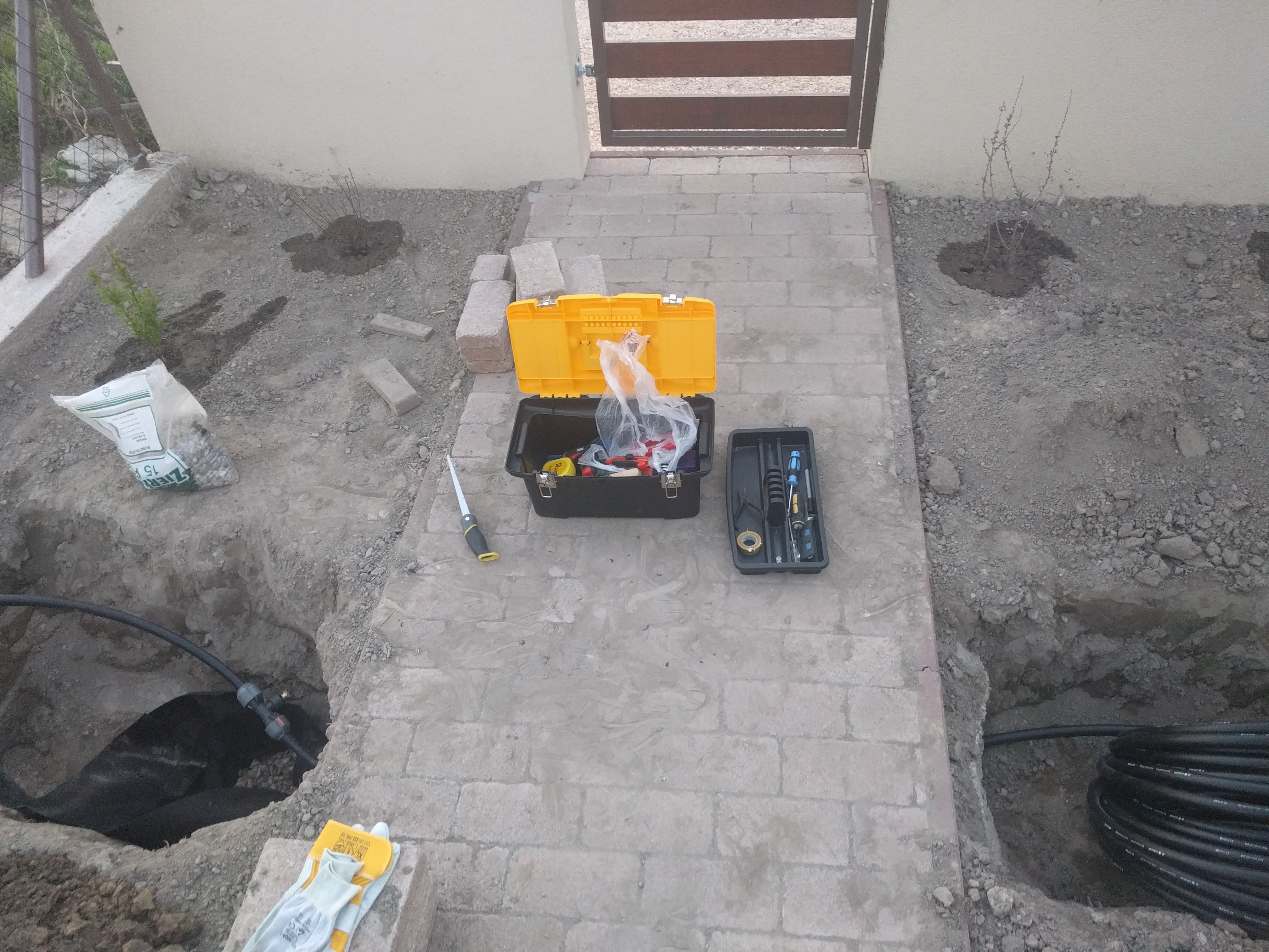
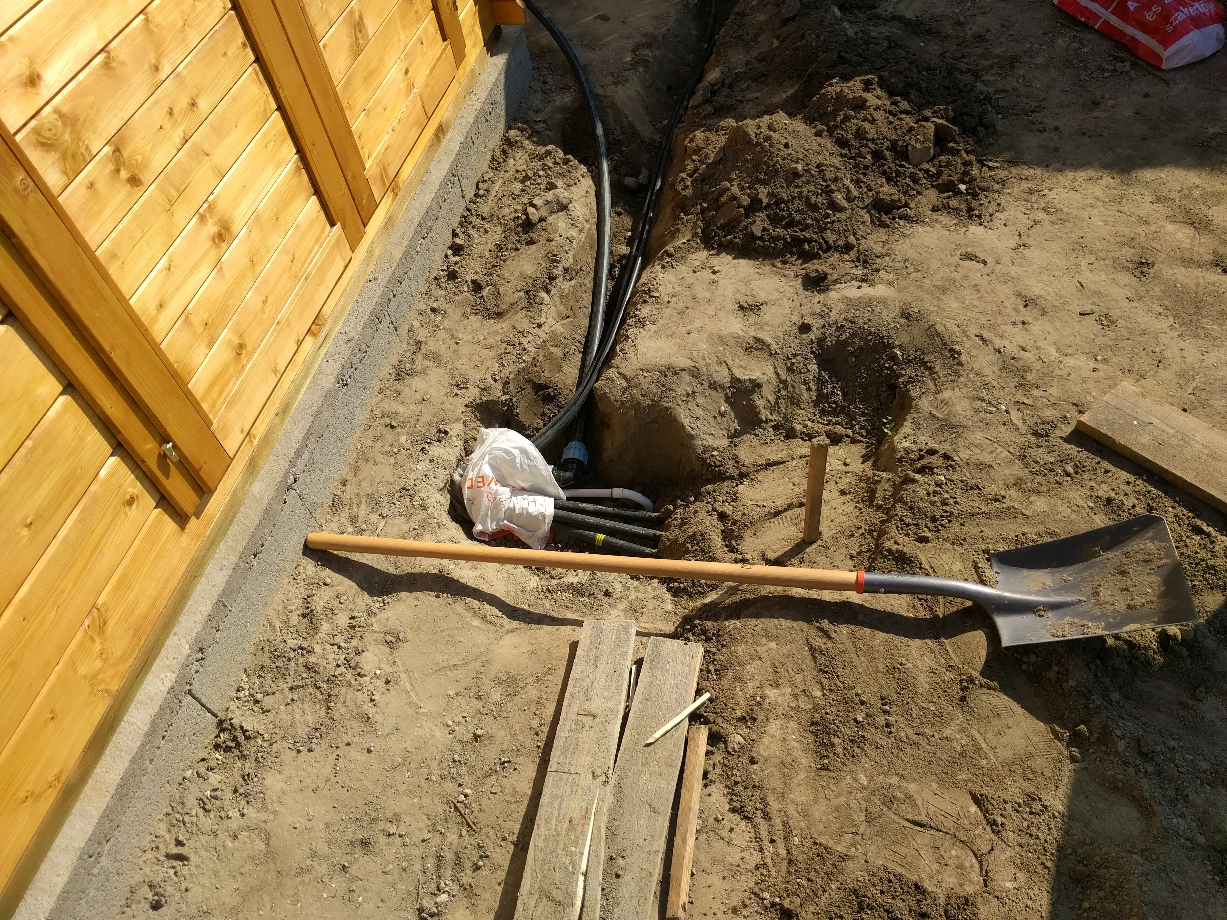 The last small hole shows where the electricity goes in and also the water comes out, directly from the pit under the ground.
The well was drilled by professionals, similarly to the wooden house building and a pit under that. The pit was designed so, that all the water related parts are fitted in. This means first of all the well, the four valves, the pump, the pressure control and all the water distributors.
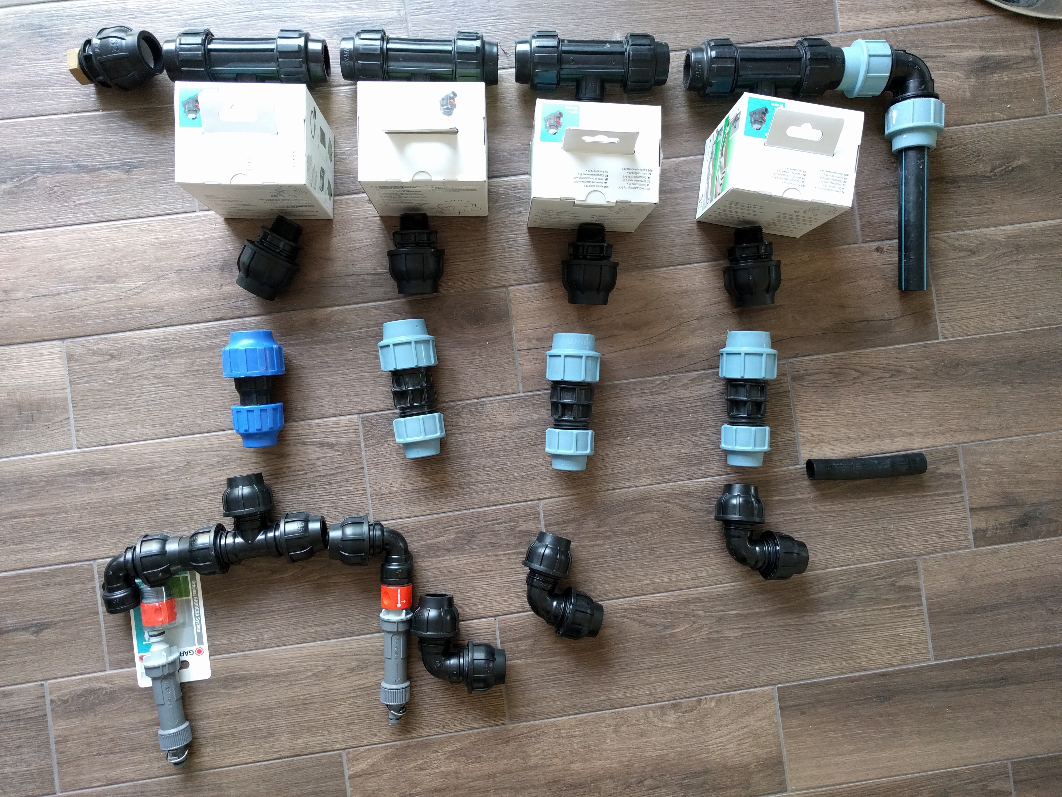 The water distribution part and the valves are…
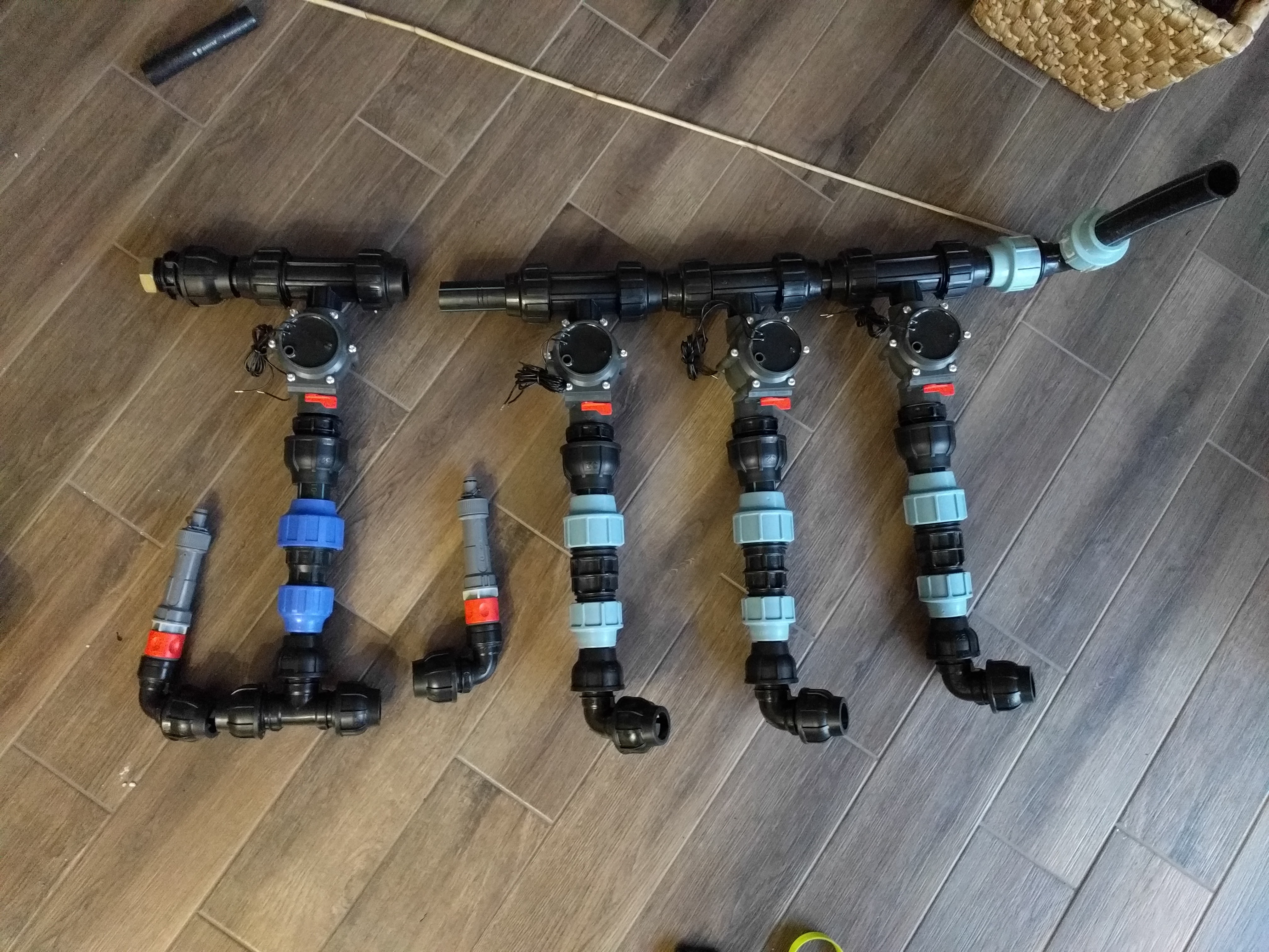 … semi-assembled.
Now let’s look inside the pit after everything is in place.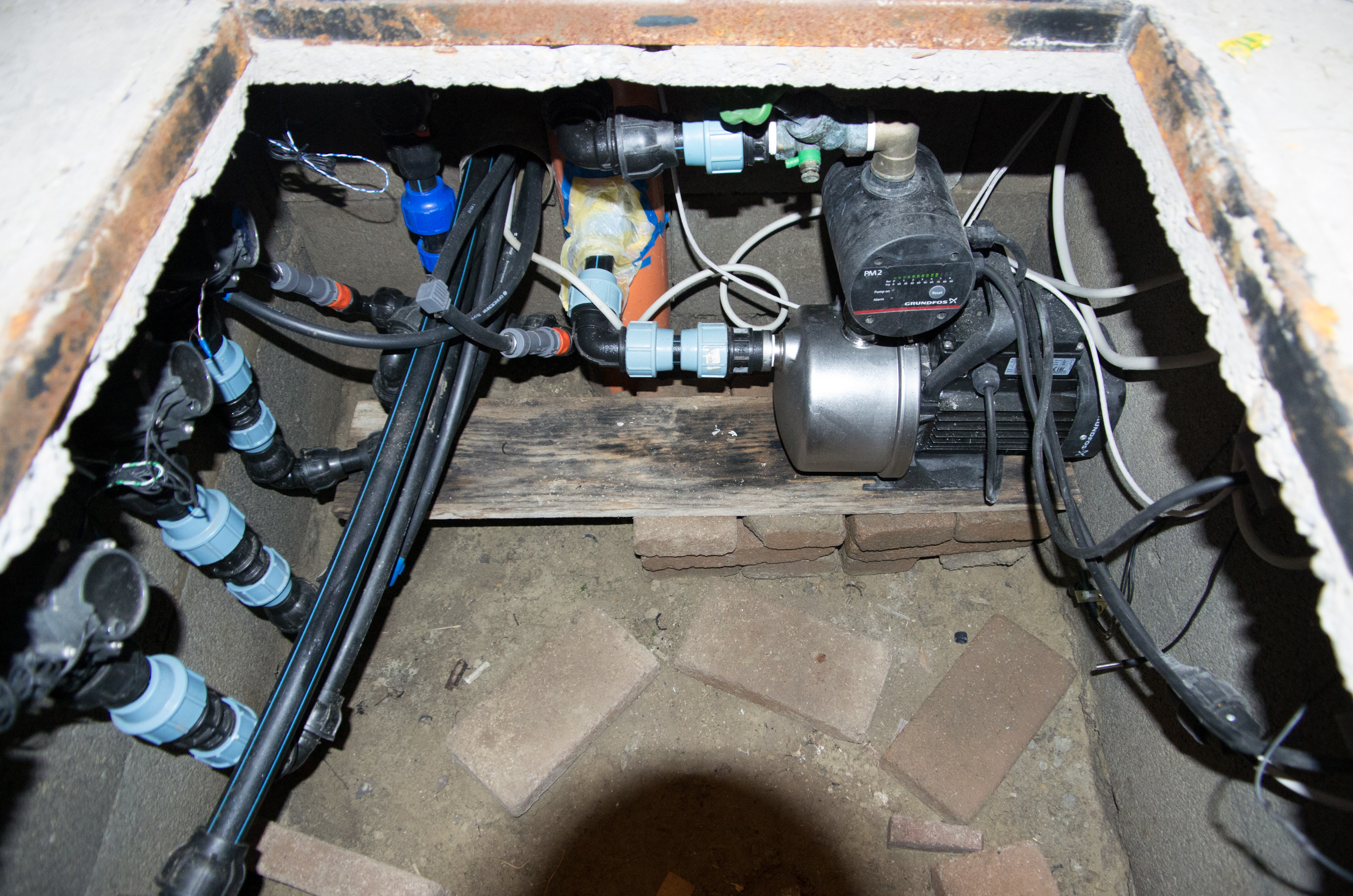
On the center we can see the well, the pump, the pressure control.
On the left hand side, there are the valves, mounted on the wall of the pit.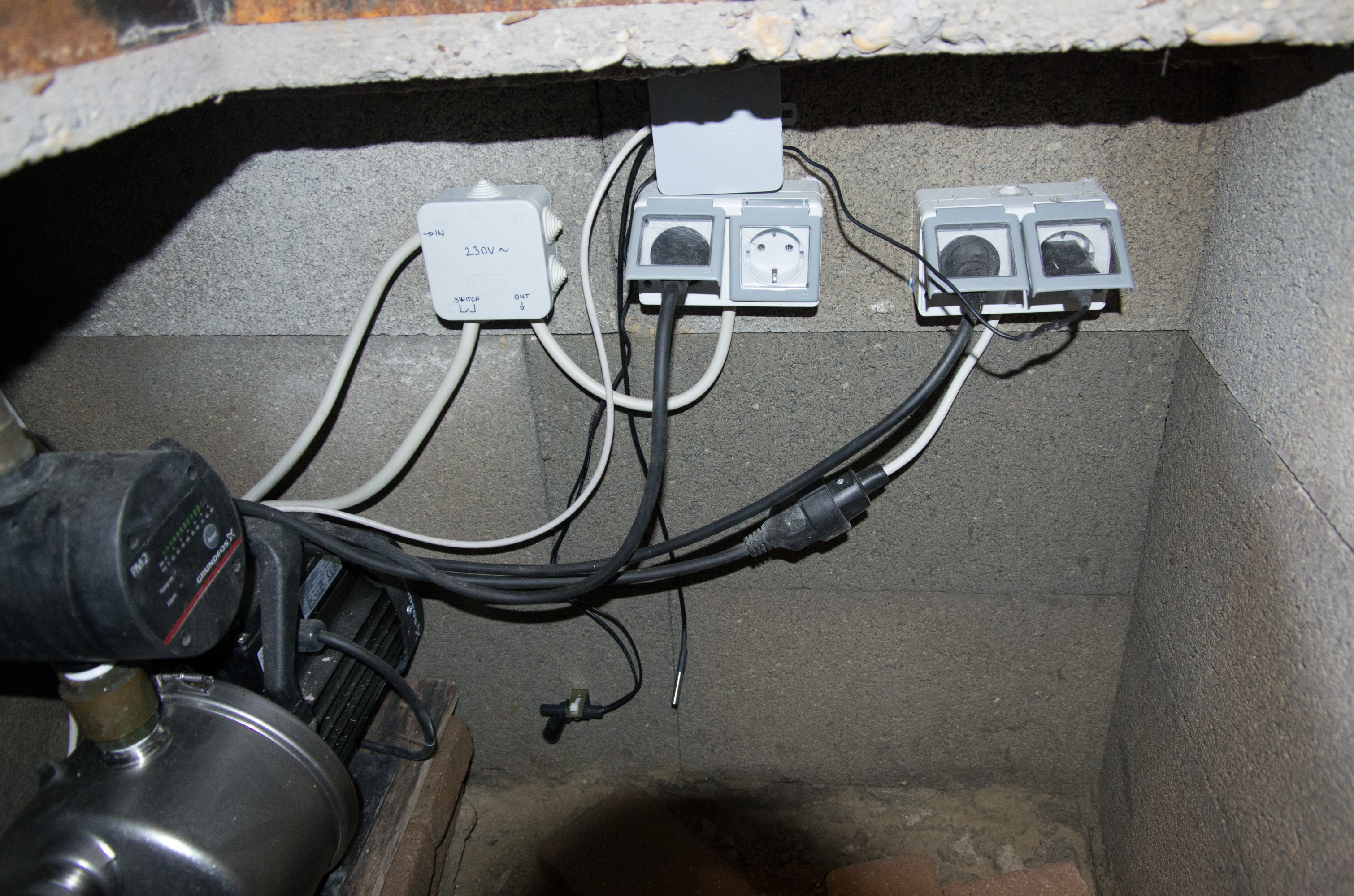 On the right hand side, there are the mains related electric parts. The two sockets on the left are regular sockets, always ON, as long as the main swift above the floor is ON. The sockets on the right are connected after the pressure controller. That means here the pump is connected, but also the mains detector, to see when the pump is ON. The water level detector and an extra temperature sensor is also here.
So the electricity is also arriving under the ground. It was previously dig in as a warmup project :). Mains is looped up over to the wooden house to get electricity for general purpose there, but also to have a big on-off safety switch for everything. There is a hole along with a piece of water pipe, used to connect the pit with the wooden house up there. There the cables for the sensors, the valves and the mains are going through.
The control hardware
I don’t want to advertise any sellers on the eBay, but you can find all the items which I built in if you want (using the search terms between “”s).
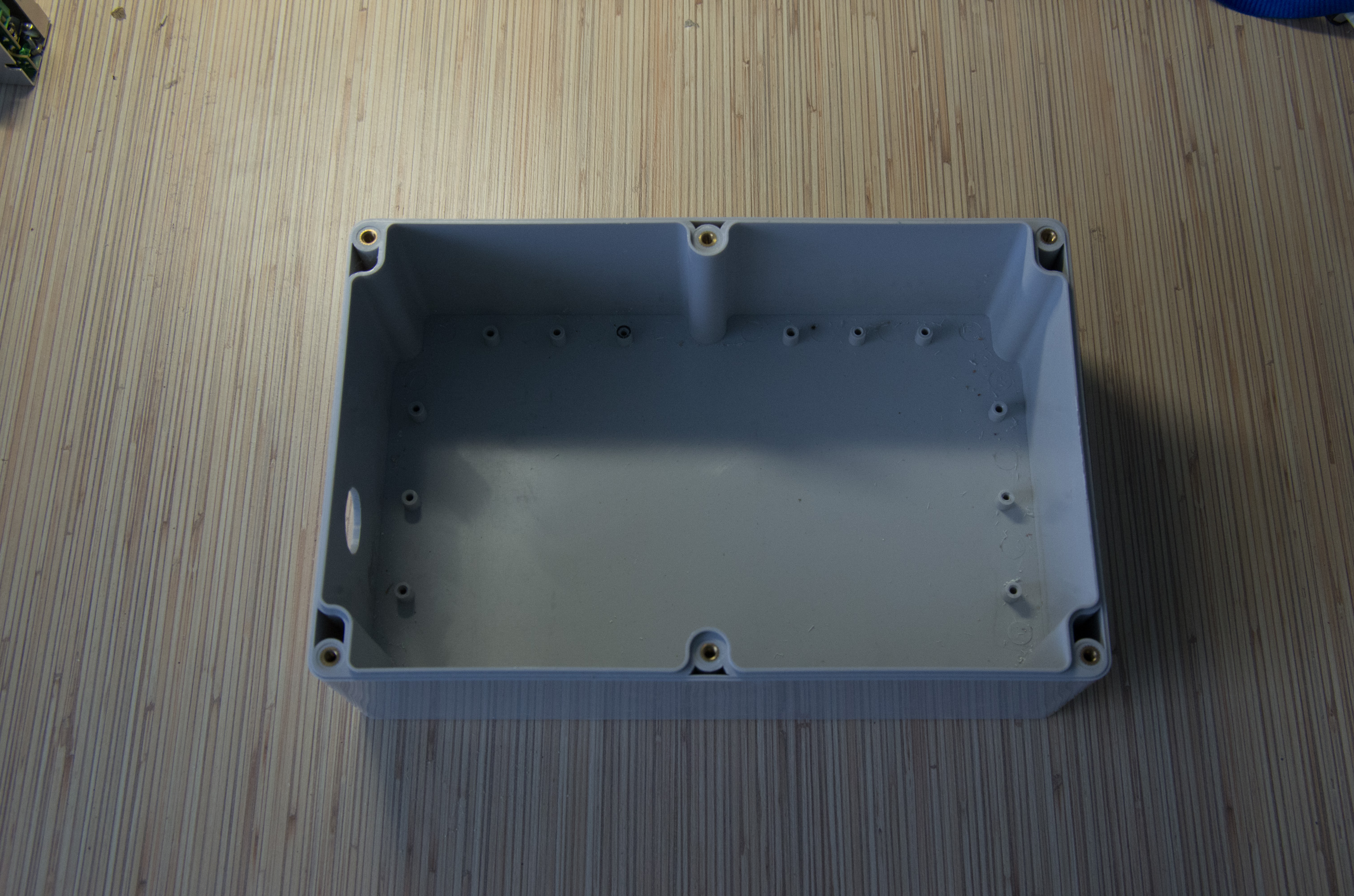
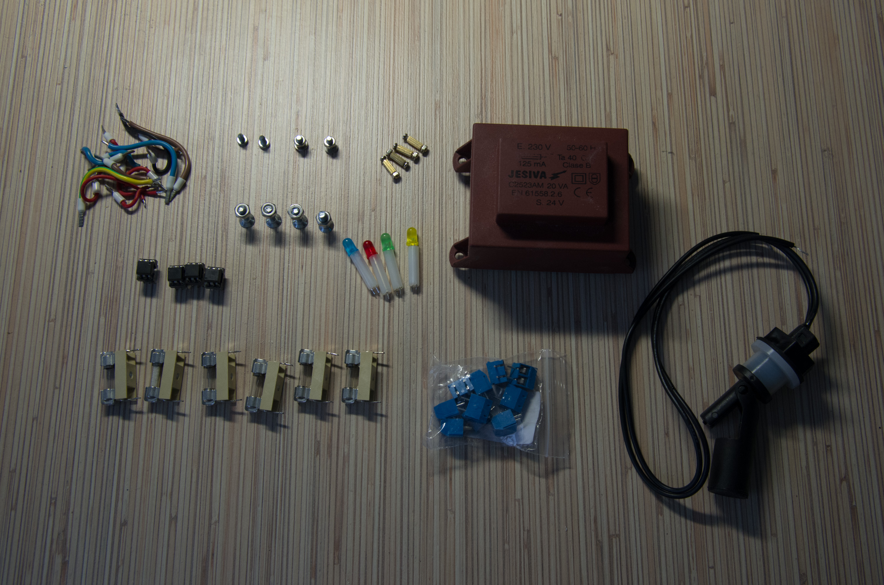
The water resistant control box is designed to embed all the electric parts, besides the valves, so at least:
- “230mmx150mmx85mm Transparent Enclosure Case DIY Electronic Wire Project Box”
- “5V 1/2/4/6/8 Channel Relay Board Module Optocoupler” - Relays to control the valves, I use 8 channel variant to have some spare for future use
- 24V AC regulator for the valves (this is from the local electronics parts store)
- Raspberry PI Zero 1.3
- A very sensitive USB WLAN stick
- “AC 110V-220V TO DC 5V 2A Switch Power Supply Driver” for the PI
- Fuses for the valve channels and for the Pi adapter
- A lot of screws, standoffs and other small parts
- Opto-couplers for the inputs to keep the Pi GPIO safe
Outside of the box, there are:
- “Water Level Sensor Horizontal Liquid PP”
- “Mini Clik Rain Sensor”
- Mains detector, USB phone charger
Now comes the extra content… I wanted extra safety for the pit, because I am not sure the water distributors are perfectly plumbed (since it is done by me :-) ). This is a problem because I have a pressure controller attached to the pump. It always measures the pressure in the outgoing pipe. When the pressure is dropped, it turns on the pump. This normally happens when the sprinkler system is activated through a valve or I want to get water from the regular faucet, also plumbed to the system. Unfortunately if anything goes wrong in the future and something is broken in the pit, the water pump might stifling itself. So TODO:
- Mains sensor for the pump. I spent quite a time surfing the internet for schematics how to detect when electricity is ON and the pump is running. Than I realized that any 5V phone charger will do the job if I connect it to the Pi’s GPIO.
- Water level sensor in the pit. If it triggers together with the pump mains detector, there is a problem for sure :).
- As a reaction, disable the pump by the spare relays when the above triggers are ON. This shall be controlled by some additional script or piece of SW on the Pi.
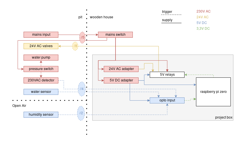
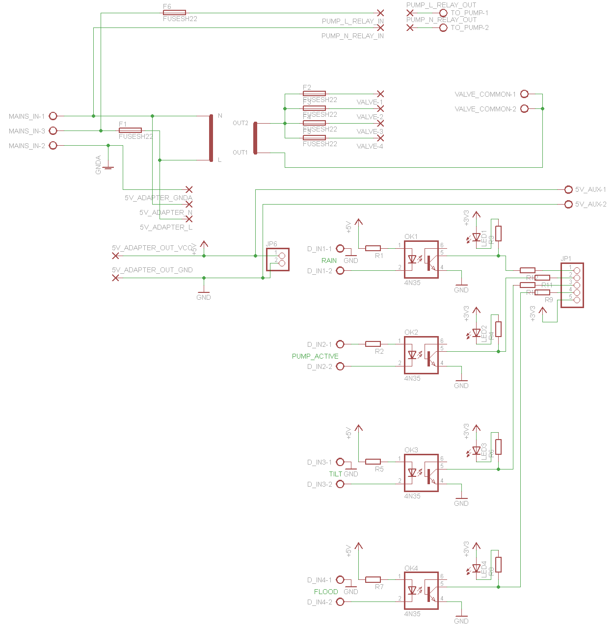
The block scheme is the following:
Schematic and board:
I waited until all the box parts have arrived and carefully measured them. Than I’ve drawn everything into the Eagle CAD project to make sure they will fit.
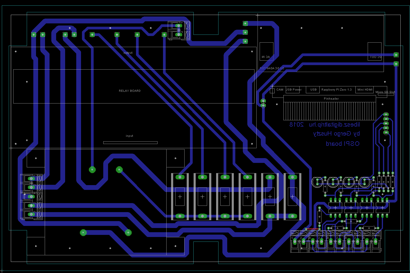
 The first two relays are expected to cut the voltage going back to the pump. It has the outgoing terminals right next to the mains input (bottom left on the board). The middle 4 relays are expected to control the valves. The relay terminals are connected to the 24V AC transformer. The 5V adapter is used to supply the Pi itself, the opto-couplers and the relay board. There is an AUX 5V terminal next to the inputs for future use.
Assembling it all together
In order to have a well organized control box, I managed to design a PCB which goes to the box and will be a kind of motherboard for all the inner parts.
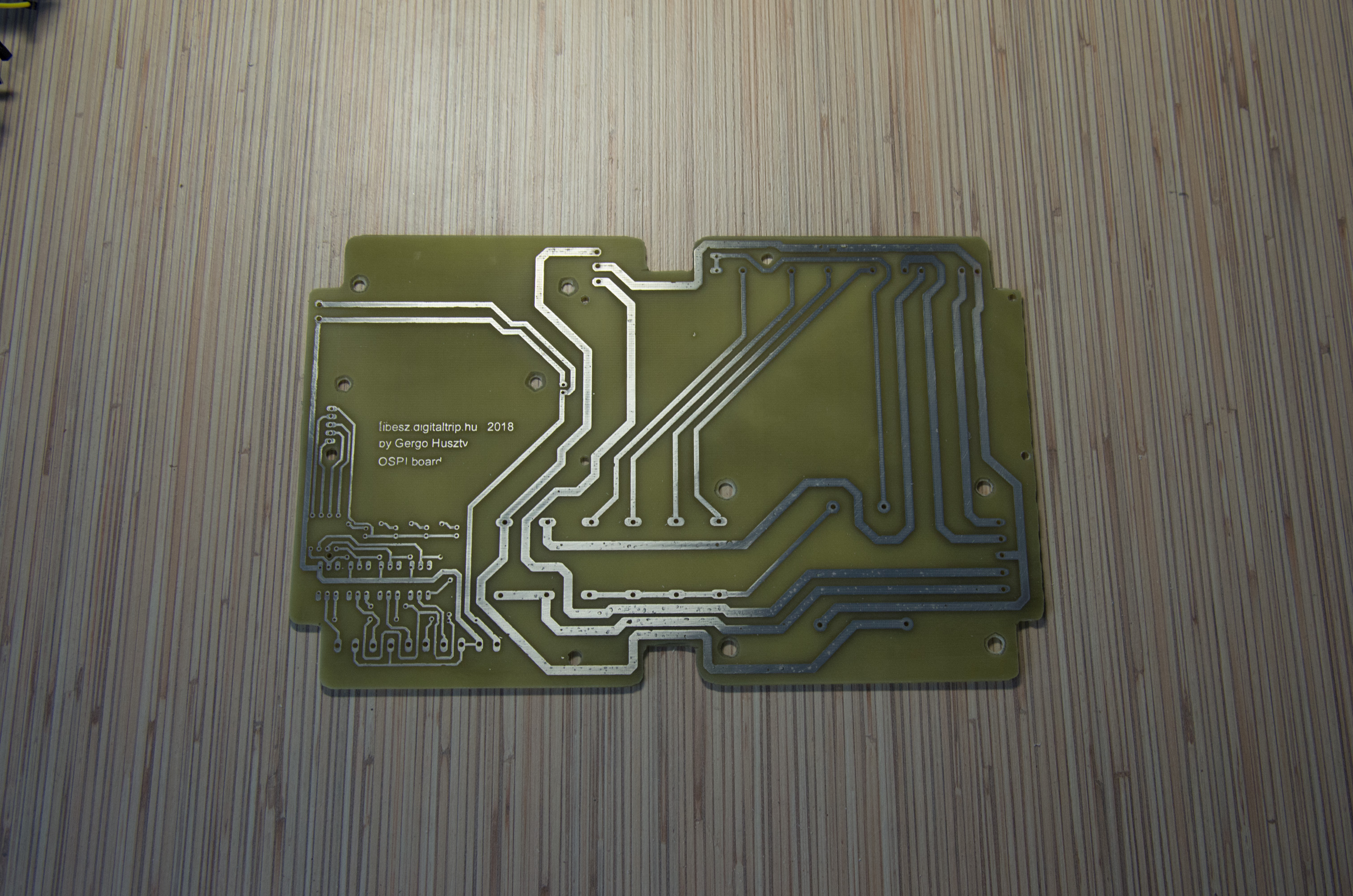

 Click on me! I’m animated.

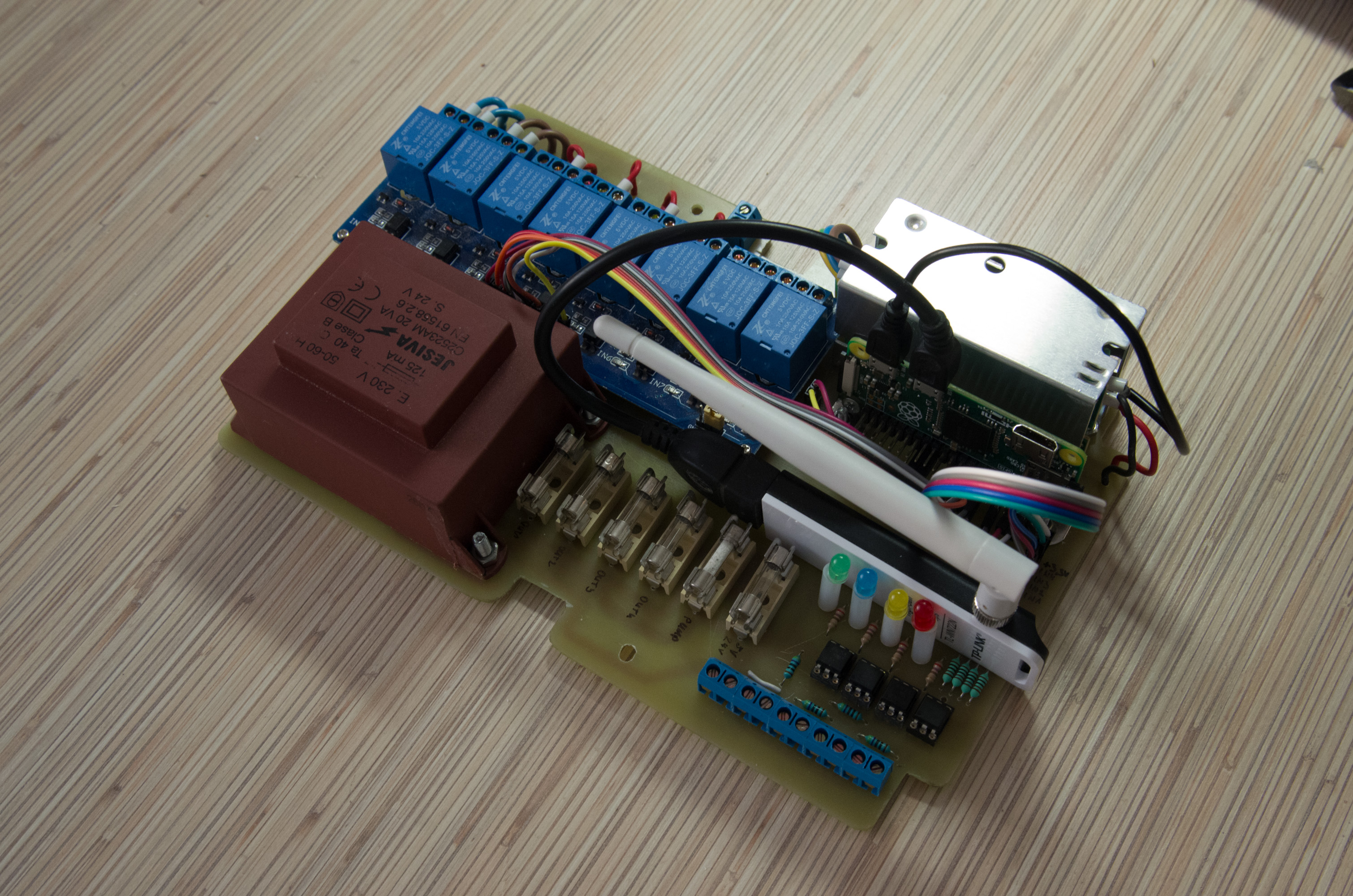
The end result, mounted on the wall:
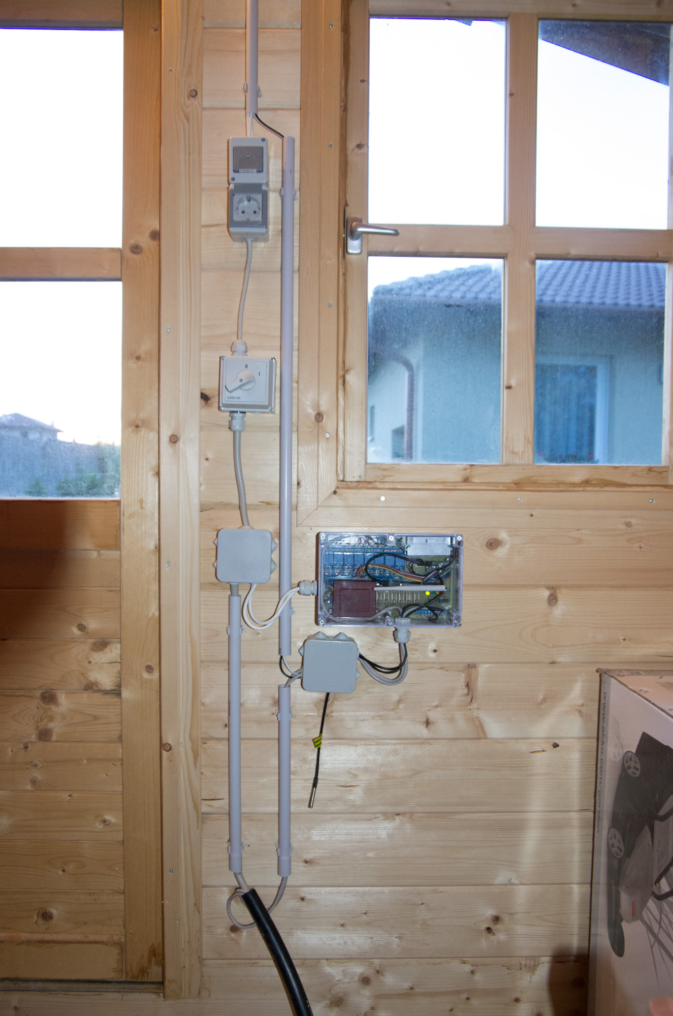 Cables are arriving from the pit in the black tube.
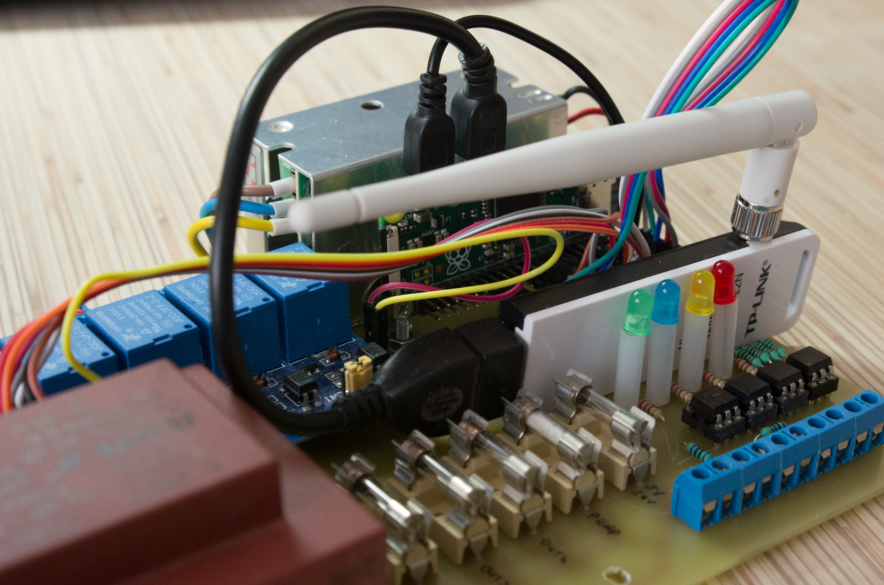
The PCB has 4 opto-coupled input with LEDs indicating if the input is active. Three of them are simple open-collector prepared, which means the input is considered as High, when the two contacts are connected together and Low, when they aren’t. No voltage expected. However there is an input on the board which expects 0-5 V TTL. This is for the USB phone charger which detects the mains on the pump. So the inputs are:
- 1: Rain sensor (open-collector). Connected to the Pi’s pin 8 (GPIO14) as OSPi expects. My rain sensor is Normally Closed, so the LED is expected to be ON when there is no rain.
- 2: Mains detector for the pump (0-5V). Connected to Pi’s pin 3 (GPIO2). So far I only created a small script to send notifications to my phone whenever the pump is activated or de-activated.
- 3: Tilt switch. Not yet used. This is going to be a simple switch crafted onto the box. If it is turned ON, all the valve outputs will be shuttled down. (open-collector)
- 4: Flood detection. Not yet used. This is connected to the water-level sensor in the pit. (open-collector)
Software
The original plan was to implement a complete REST API and a fancy dynamic web page on top, but when I found the OpenSprinkler project out there, I decided that I will use it. I installed the regular Raspbian OS on the Pi and the OSPi software (also called SIP) onto it. See below.
Open Sprinkler is originally a microcontroller based product, but it has a Raspberry PI based pure python SW implementation (OSPi). Here you can find the project. By default, it uses a 74HC595 shift registers to have a very flexible solution, as it can be extended by just using more 595s without exhausting the Pi pins. However I only have 4 valves so I wanted to spare the shift register and more importantly the space for it in the box. As you can see the box is totally filled up. Fortunately there is an official plugin for OSPi especially for this purpose. This plugin substitutes the original valve channels in the SW and you can use without noticing any change on the GUI. It will use a pin directly to control each relays without shift register.
TODO list:
The pump and the valves tilt logic are not yet in place. Basically these are the only remaining tasks and the project is ready.
Also, I might missed important details to document. If anything missing and you want to re-build the solution, feel free to ask in comment!
Downloads:
You can download the eagle project with all the properly sized parts inside here.